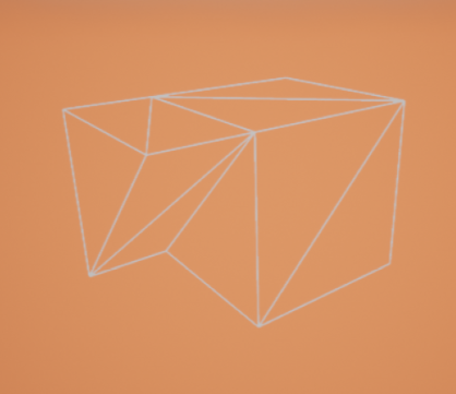
A virtual-reality modeling tool in Unreal that showcases the CGoGN library and the combinatorial-maps data structure, from topological analysis to real-time mesh editing in VR.
For this project I was tasked with building a demo of a virtual-reality modeling tool that highlights the strengths of the CGoGN[1] library and the combinatorial-maps data structure. CGoGN is a C++ library developed by the University of Strasbourg[2] for representing meshes with combinatorial maps. The work spanned two halves: understanding and exposing the topological data structure, and designing ergonomic modeling interactions inside Unreal Engine[3] for use in VR.
CGoGN and combinatorial maps
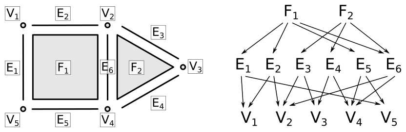
At its core, CGoGN uses an n-dimensional cell decomposition of an object and defines cell-tuples to derive incidence and adjacency relations between cells.
A cellular decomposition of an object in 2D and its incidence graph.
Cell-tuples and generalized maps
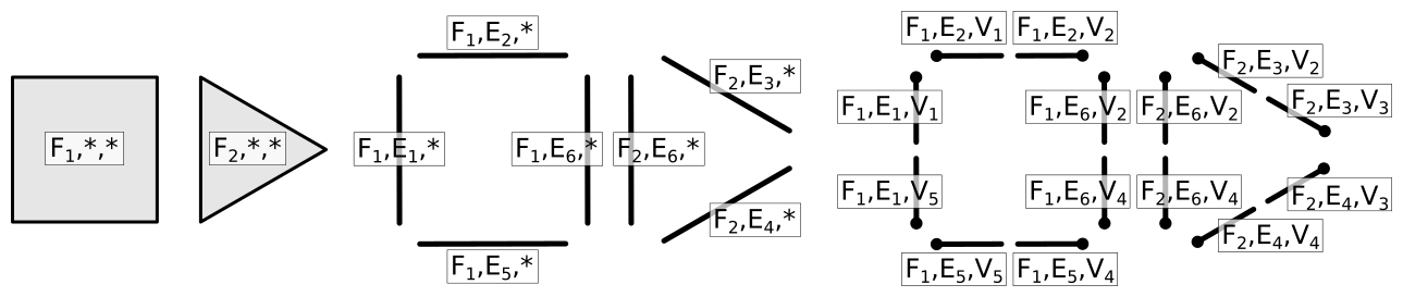
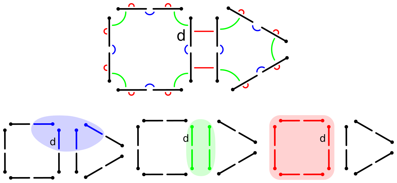
In an n-dimensional cell decomposition, a cell-tuple is a sequence of cells (Cₙ, Cₙ₋₁, …, C₁, C₀) such that each Cᵢ is incident to Cᵢ₋₁, effectively a path through the object’s incidence graph. To represent these cell-tuples compactly, CGoGN uses generalized maps: a list of darts where one dart corresponds to one cell-tuple, together with n+1 involutions αᵢ (for 0 ≤ i ≤ n) defined on the i-adjacency of cell-tuples, used to traverse the object.
Construction of the cell-tuples of the previous figure.
The generalized map of the first figure.
Orienting the map
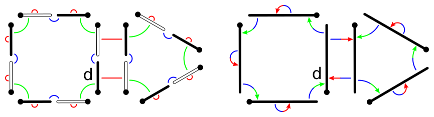
Generalized maps can represent both orientable and non-orientable topology. By restricting ourselves to orientable surfaces (sufficient for the vast majority of applications), we can use a more compact model: oriented combinatorial maps. The darts split into two groups such that a dart in one group only links to darts in the other; both groups describe the same shape, so we simply keep one of them.
The oriented combinatorial map of the previous figure.
Attaching attributes
These maps only encode topology. To attach attributes to a cell (a vertex position, for instance), the attribute must be shared by every dart of that cell. CGoGN solves this by assigning an index to each cell, so all darts of all dimensions belonging to the same cell share the same index.
Displaying mesh information
Topological readouts
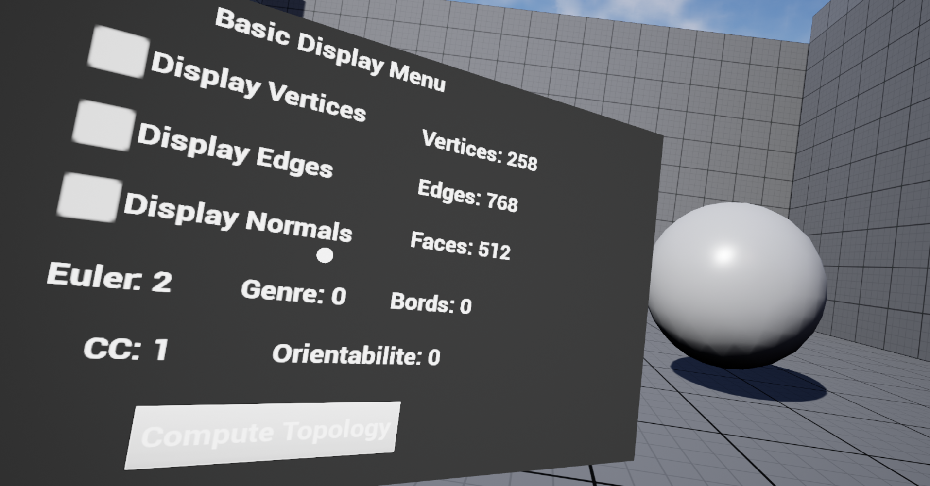
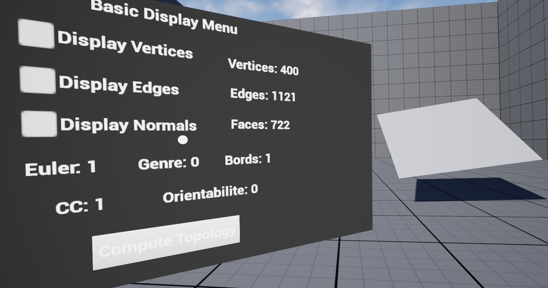
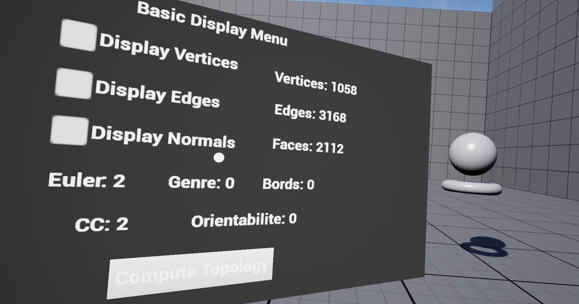
The first way I exposed the data structure was a menu surfacing topological information about the current mesh: not just the counts of vertices, edges and faces, but several derived quantities.The Euler-Poincaré[4] characteristic χ, from the vertex (V), edge (E) and face (F) counts:
χ=V−E+FEuler-Poincaré characteristic.
The genus g (number of handles) of an orientable surface, derived from χ, the number of boundaries b and the orientability o:
g=1−2χ+b+oGenus of an orientable surface.
The number of connected components, computed by a flood-fill over the vertex-adjacency relations, where the component count equals the number of diffusions needed to reach every vertex. The number of boundaries leans on a CGoGN specificity: a 2-map cannot normally have a border, but CGoGN allows borders via invisible faces, so the boundary count maps directly to the number of invisible faces stored in the map. Finally, orientability, which here is always true, since CGoGN only handles orientable surfaces.
Sphere
Plane
Multiple components
The topology readout for a sphere, a plane, and a mesh with several connected components.
Displaying cells with GPU instancing
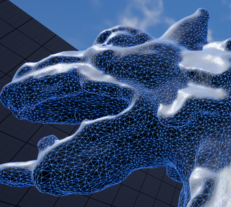
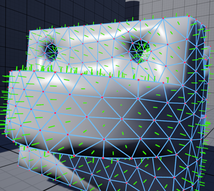
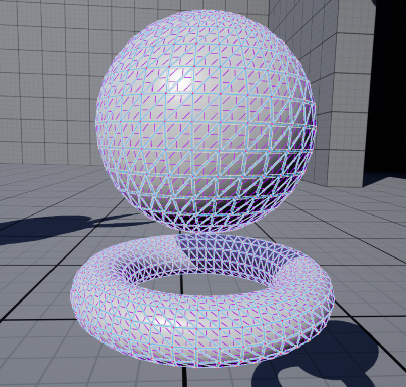
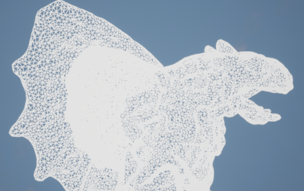
To make the features usable during interaction, I built a real-time display of the mesh’s cells. Rendering large numbers of cells live calls for GPU instancing: drawing many copies of a single mesh in one render call, which minimises CPU-GPU communication and cuts draw time. Unreal exposes tooling for this, which I leveraged to display vertices, edges and face normals.
Vertices and edges (300k+)
Face normals
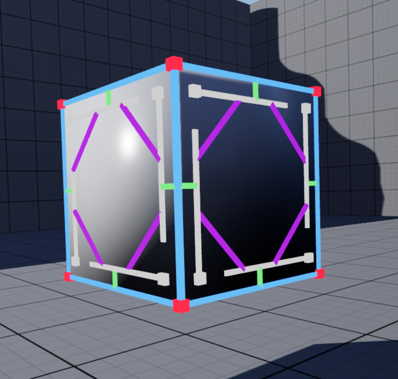
Over 300,000 vertices and edges displayed in real time via GPU instancing (left); the same technique also renders the face normals (right).The same instancing approach visualises the CGoGN structure itself, drawing the darts and their φ₁ and φ₂ relationships and turning an abstract data structure into something you can inspect directly in the scene.
The darts (cell-tuples) and their φ₁ and φ₂ links, drawn with the same instancing.
Interactions and modeling
Proportional affine transformations
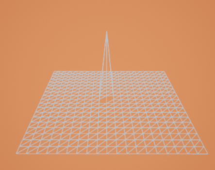
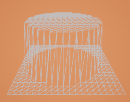
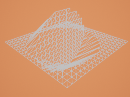
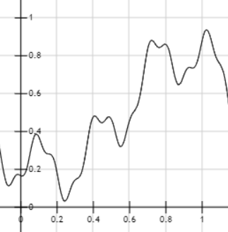
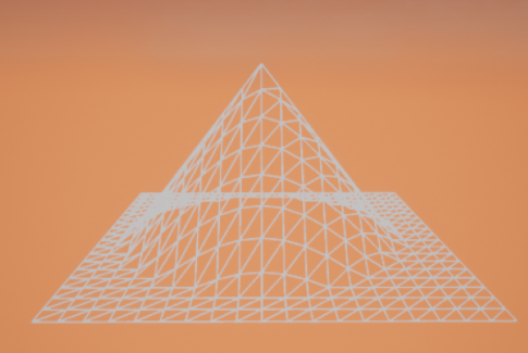
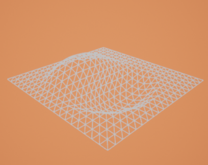
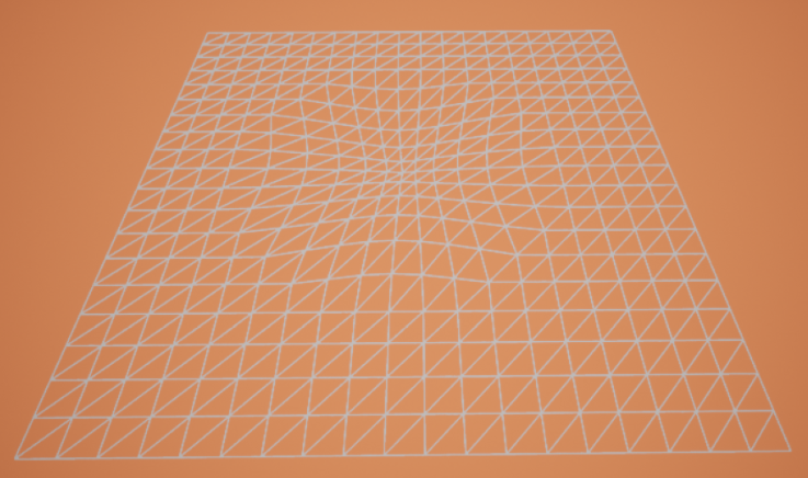
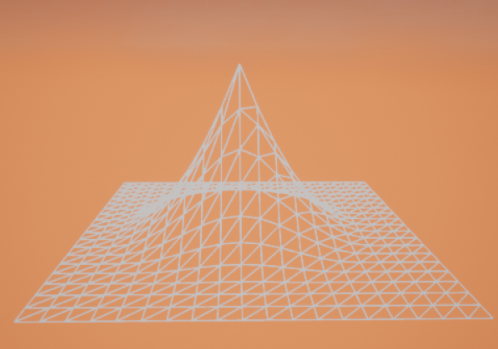
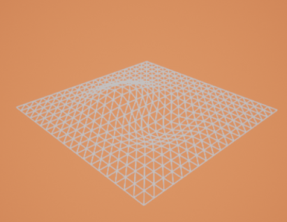
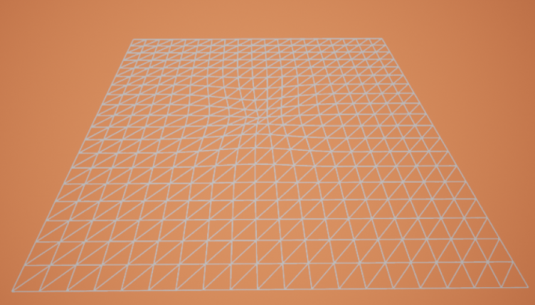
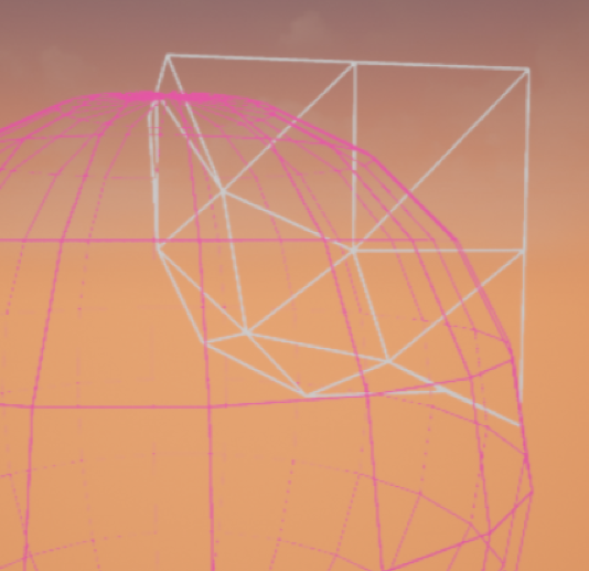
Translation, rotation and scaling are the bread and butter of 3D modeling, so I implemented all three, and to put CGoGN’s topology to work, added a proportional-editing mode inspired by Blender[5]. It defines a sphere of radius R around the origin cell within which every vertex is transformed proportionally to a chosen falloff. With D the distance from a vertex to the origin cell, the user can pick from seven proportion modes:
Constant - always equal to 1:p=1
Random - a random proportion
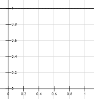
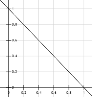
Linear - falls off with distance:p=1−RD
Power - the linear criterion squared:p=(1−RD)2
Root - the square root of the linear criterion:p=1−RD
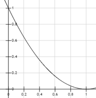
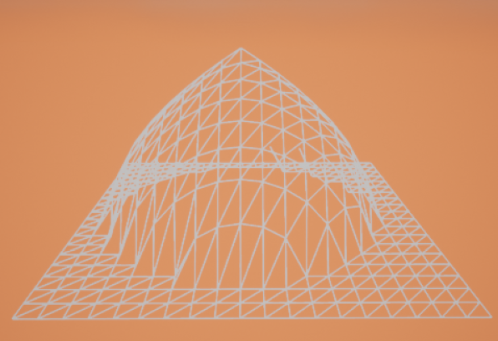
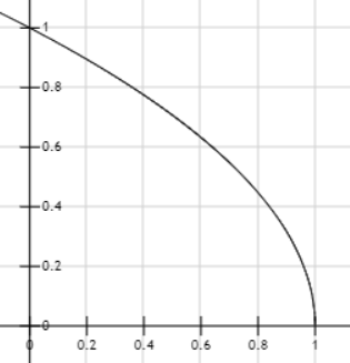
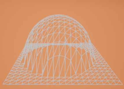
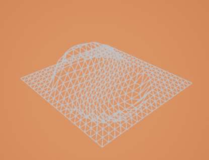
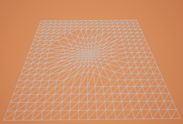
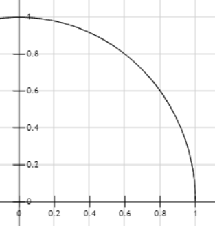
Sphere - traces a spherical arc:p=2(1−RD)−(1−RD)2
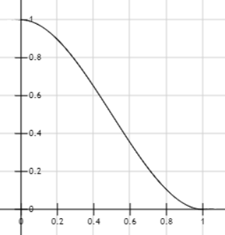
Smooth - the smoothest possible falloff:p=3(1−RD)2−2(1−RD)3
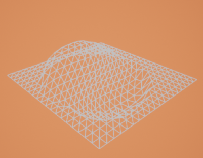
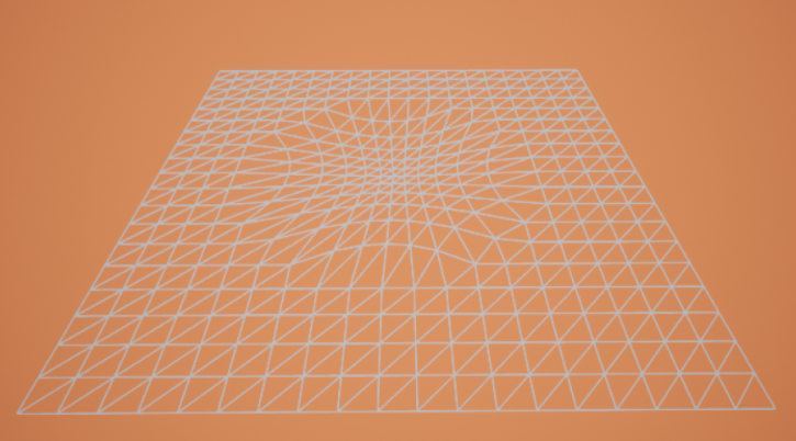
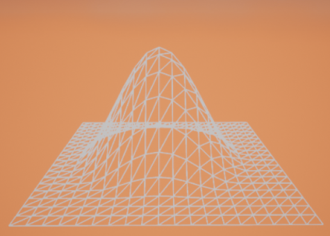
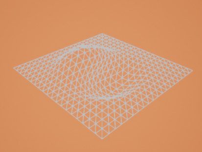
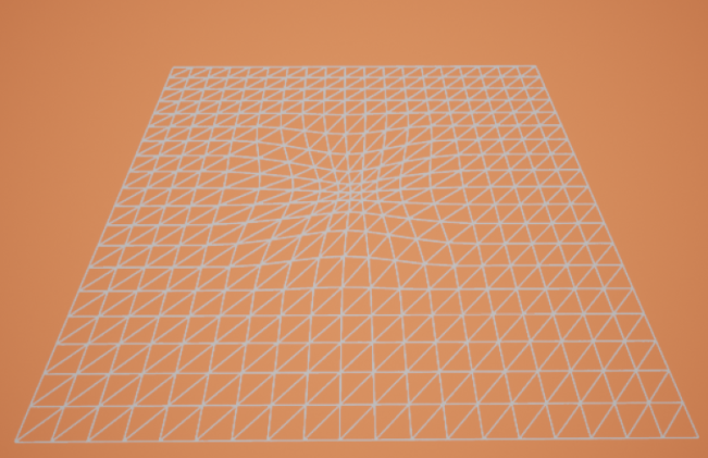
To gather the vertices inside the sphere, I use a flood fill with an explicit stack over CGoGN neighbourhoods, so there is no need to test every vertex in the object, a major performance win. The origin cell can be a vertex, edge or face; the behaviour stays consistent across all three.Each mode is shown below applied to a translation, a rotation and a scaling, next to its falloff curve.
Translation
Rotation
Scaling
Curve
No criterion: the whole selection transforms uniformly.
Translation
Rotation
Scaling
Curve
Constant falloff (p = 1).
Translation
Rotation
Scaling
Curve
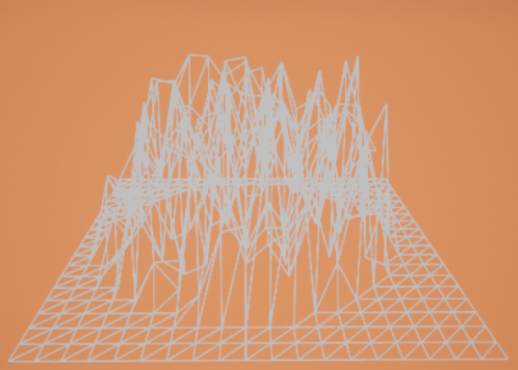
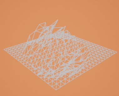
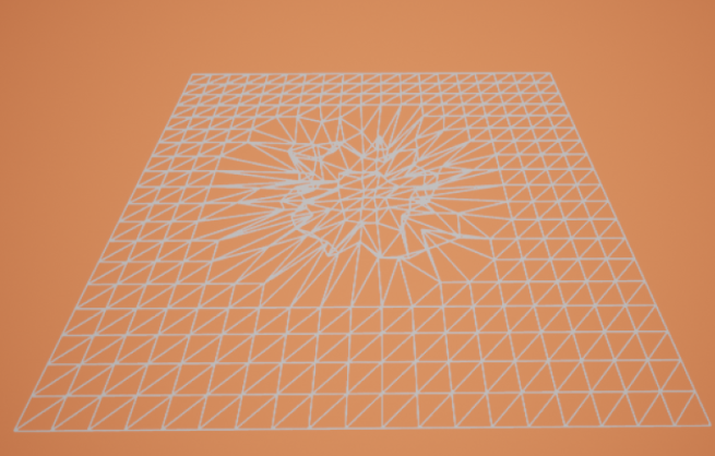
Random falloff.
Translation
Rotation
Scaling
Curve
Linear falloff (p = 1 - D/R).
Translation
Rotation
Scaling
Curve
Power falloff.
Translation
Rotation
Scaling
Curve
Root falloff.
Translation
Rotation
Scaling
Curve
Spherical falloff.
Translation
Rotation
Scaling
Curve
Smooth falloff.
Laplacian smoothing
To let users smooth a model easily, I implemented uniform-weight Laplacian smoothing[6], the simplest formulation, where each vertex moves to the average position of its neighbours:
xˉi=N1j=1∑NxˉjUniform Laplacian smoothing: N is the neighbour count of vertex i.
As with the transforms, smoothing can be restricted to the vertices contained within a sphere, so users can soften a local region without touching the rest of the mesh.
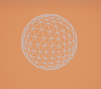
Original
1 iteration
1 iteration, in a sphere
A mesh (left), after one Laplacian smoothing iteration (middle), and one iteration restricted to a sphere (right).
Subdivision
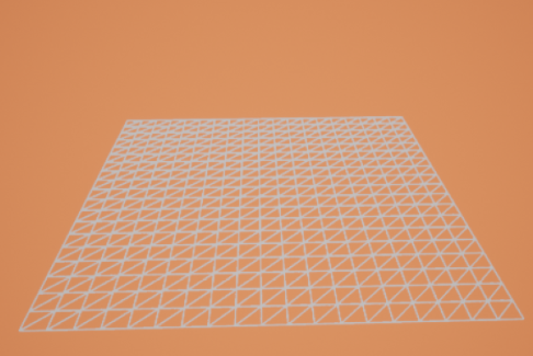
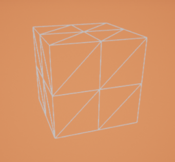
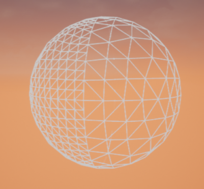
Moving from geometry to topology, I added a subdivision operator using the simplest scheme: every edge is split in two with the new vertex at its midpoint. This leaves the geometry untouched and only adds vertices. CGoGN lets me traverse and cut each edge exactly once (ignoring the freshly created ones), and the operation can again be confined to a spherical region.
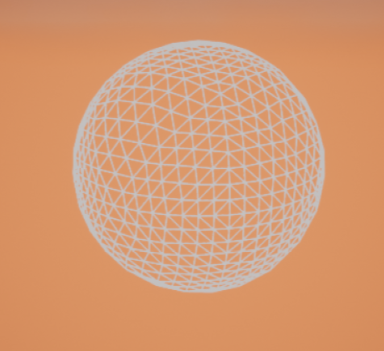
Original
Subdivided
Subdivided in a region
A mesh (left), its subdivision (middle), and a subdivision confined to a region (right).
Decimation
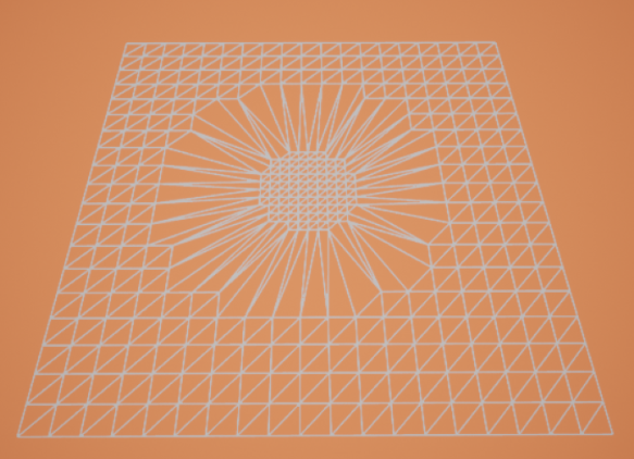
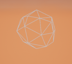
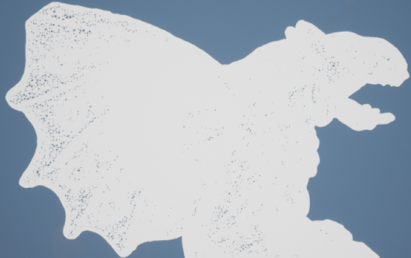
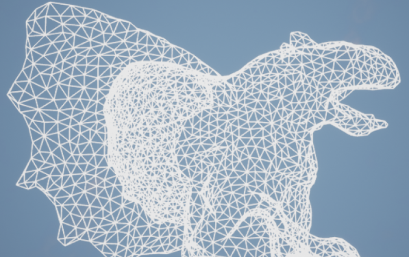
As the counterpart to subdivision, I implemented simplification by decimation. It iteratively collapses the lowest-cost edges, where cost is the edge length, placing the resulting vertex at the midpoint of the collapsed edge. The user controls the stopping criterion: either a target number of vertices to remove, or a maximum edge length allowed to collapse.
Base mesh
70,000 removed
95,000 removed
100,000 removed
Progressive edge-collapse decimation: the base mesh, then 70,000, 95,000 and 100,000 vertices removed.
Extrusion
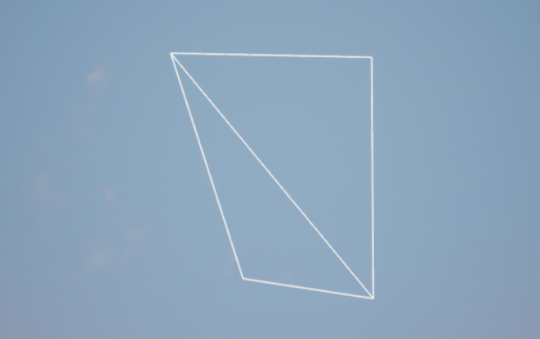
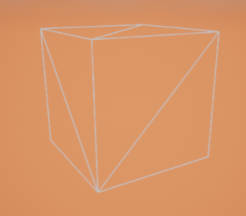
Finally, I added extrusion for its intuitive feel: select a face, duplicate its vertices, offset them along an input vector, and create new faces to bridge the old and new vertices.
Before
After
A face before and after extrusion.
Virtual reality interactions
Every feature was built under the constraint of being usable in virtual reality. A large share of the work went into ergonomic VR interactions and a graphical interface that makes each feature easy to reach with motion controllers: grabbing, transforming, smoothing, extruding and inspecting topology directly in 3D space. Balancing precision with comfort was as much a design challenge as the underlying data structure.A short showcase of the finished VR modeling tool.